
TECHNO ANALYSIS SDN BHD

TUBING INSPECTION
"Uncover defects and identify critical downhole conditions"
INTERNAL ROTARY INSPECTION SYSTEM (IRIS)
Scans:

Interpreting Results

Advantages of IRIS:
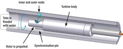
The Internal Rotary Inspection System (IRIS) technique is based on ultrasonic principles. As shown in the above illustration a beam from an ultrasonic transducer is reflected from a mirror set at 45 degrees so that the reflected ultrasonic beam impinges on the tube I.D. at right angles. Part of this beam is then reflected from the tube I.D., while the remainder is transmitted through the wall thickness and is reflected from the tube O.D. The time difference between the two reflected signals is then used to measure the tube wall thickness. The mirror is mounted on a water driven turbine that rotates at speed of about 2,000 rpm. Measurements are then made around the full tube circumference and as the probe head is pulled through the tube the ultrasonic beam maps out a spiral along the tube length. If the probe pulling speed is sufficiently slow, taking into account the inspection parameters, a 100 % coverage of the tube surface is achieved.
With advanced software, results can be displayed in a number of views as illustrated below.
The C scan presentation provides a plan view of the tube as if it has been rolled flat. Colour coding is used to display the wall thickness as illustrated by the rainbow of colours displayed in the icon.
The B scan display provides a 2 dimensional display of a transverse cut through the tube at any desired position along the tube length.
The D scan display provides a 2 dimensional display of a longitudinal cut through the tube at any desired circumferential position on the tube.
The real time C-Scan can best be explained as seen below. Here is a sample tube “cut” along the longitudinal axis, un-rolled and flattened out to reveal a plot view the colour model being the actual result.
-
Very accurate technique. Wall thickness measurements can be made to an accuracy within 0.1 mm.
-
Fairly sensitive technique. The sensitivity achieved will depend on tube dimensions and tube cleanliness. In general it can be stated that it should be possible to detect a 1.5 mm defect in up to 1 inch tubing that has been properly cleaned.
-
A 3-dimensional picture of the defect is obtained. Thus the defect profile in addition to its depth is obtained.
-
Interpretation of results is easier than in the other techniques assuming that reasonable tube cleanliness has been achieved.
-
Ferromagnetic and non-ferromagnetic tubes can be inspected.

TECHNO ANALYSIS SDN BHD
Our company are lead by experienced personnels in NDT field with more than 13 years of experience in the industry. We are committed in performing high quality NDT inspection services on our customer’s products for integrity, safety and reliability.
NAVIGATOR
CONTACT US
50-3, Jalan Wangsa Delima 5,
Seksyen 5, Wangsa Maju,
53300, Kuala Lumpur.
Tel : +6 03 4143 3703
Email: inquiry@technoanalysis.com.my